Couplers (Broadwall, Sidewall, Crossguide & Loop)

We offer a range of directional broad wall, side wall and cross guide couplers in 3 and 4 port configurations.  All couplers have been designed to offer low VSWR, flat... Read full description

SKU: couplers

Categories: Waveguides

Description

We offer a range of directional broad wall, side wall and cross guide couplers in 3 and 4 port configurations.  All couplers have been designed to offer low VSWR, flat response and high directivity over the entire designated waveguide band. Improvements in directivity and coupling value tolerances can be made for specified narrow band applications. The CC and DC series of couplers are manufactured with the full range of international flange styles as shown in our Flange Catalogue with alternative plating and paint finishes on request.

Cross Guide Couplers (3 Port)

Standard Rectangular

Standard Rectangular diagram

Specification:
Standard Coupling Values: 20dB, 30dB, 40dB
Nominal accuracy: ±.1dB, ±.1.5dB, ±.1.5dB
V.S.W.R.: 1.32max, 1.22max, 1.06max
Directivity: 20dB typical
Material: Brass
Finish: Blue Paint
3 port couplers have an internal load to give the best directivity performance.

Operating Frequency Band (GHz) Waveguide Designation Dimension (mm)
UK WG IEC R E.I.A. WR A B C D
2.60 – 3.95 10 32 284 334 204 36 229
3.30 – 4.90 11A 40 229 288 153 31 212
3.95 – 5.85 12 48 187 248 153 24 172
5.85 – 8.20 14 70 137 192 102 17 141
7.05 – 10.0 15 84 112 167 102 14 116
8.20 – 12.40 16 100 90 141 76 12 103
10.0 – 15.0 17 120 75 121 76 11 82
12.4 – 18.0 18 140 62 111 76 9 73
18.0 – 26.5 20 220 42 81 57 5 54
26.5 – 40.0 22 320 28 79 51 5 54

Available in 20, 30, and 40 dB Coupling only.
For other Coupling values contact our sale team.
Please state the frequency bandwidth you require when ordering.

Cross Guide Couplers (4 Port)

Standard Rectangular

Cross Guide Couplers (4 Port) diagram

Specification:
Standard Coupling Values: 20dB, 30dB, 40dB
Nominal accuracy: ±.1dB, ±.1.5dB, ±.1.5dB
V.S.W.R.: 1.29max, 1.17max, 1.06max
Directivity: 20dB typical
Material: Brass
Finish: Blue Paint
The installed directivity of 4 port couplers depends on the match seen at the opposite arm.

Operating Frequency Band (GHz) Waveguide Designation Dimension (mm)
UK WG IEC R E.I.A. WR A B C
2.60 – 3.95 10 32 284 204 204 36
3.30 – 4.90 11A 40 229 153 153 31
3.95 – 5.85 12 48 187 153 153 24
5.85 – 8.20 14 70 137 102 102 17
7.05 – 10.0 15 84 112 102 102 14
8.20 – 12.40 16 100 90 76 76 12
10.0 – 15.0 17 120 75 76 76 11
12.4 – 18.0 18 140 62 76 76 9
18.0 – 26.5 20 220 42 57 57 5
26.5 – 40.0 22 320 28 51 51 5

Available in 20,30, and 40 dB Coupling only.
For other Coupling values contact our sales team.
Please state the frequency bandwidth you require when ordering.


Ordering information

Example: CC 16 A Q Z 402 402 402 402 B 40

  • FA
    • Product code:
      CC = cross guide coupler
  • 16
    • Waveguide size:
      British WG size for rectangular waveguide or MIL spec. WRD size for double ridge waveguide
      e.g. 16 = WG16; 750 = WRD750
  • S
    • Type:
      A = standard 3 port
      B = standard 4 port
  • Q
    • Paint:
      Q = TWS blue (preferred)
      B = black
      G = grey
  • Z
    • Finish:
      Z = unplated (preferred for brass / copper)
      M = passivate (option for brass)
      F = Iridite (preferred for aluminium)
      H = chromate
      A = tin
      B = silver
  • 402
    • Flange type  (through arm - input arm):
      Last 3 digits from the TWS flange part no.
      e.g. 402 = UBR flange
  • 402
    • Flange type (through arm - output):
      Last 3 digits from the TWS flange part no.
      e.g. 402 = UBR flange
  • 402
    • Flange type  (coupled arm):
      Last 3 digits from the TWS flange part no.
      e.g. 402 = UBR flange
  • 402
    • Flange type (reverse coupled) - 4 port coupler only):
      Last 3 digits from the TWS flange part no.
      e.g. 402 = UBR flange
  • B
    • Material:
      A = aluminium
      B = brass
  • 40
    • Coupling Value
      20 = 20dB
      30 = 30dB
      40 = 40dB

Directional Couplers (3 Port) broadwall

Standard Rectangular

Directional Couplers (3 Port) broadwall

Specification:
Standard Coupling Values: 10dB, 20dB, 30dB, 40dB
Nominal accuracy: ±.1.5dB, ± 1.5dB, ±.2dB, ± 2dB, WG20 -WG22 ±.2dB
Return loss secondary arm: 27dB min
Flatness: ±.1dB
Directivity
WG 10 - 18 : 35dBmin over 75% bandwidth
WG 20 - 22 : 30dBmin over 50% bandwidth
full band spec. :  see table
Material: Brass
Finish: Blue Paint

Operating Frequency Band (GHz) Waveguide Designation Directivity Minimum (dB) (2) Return Loss (Primary) (dB) Dimension (mm)
UK WG IEC R E.I.A. WR A B C
2.60 – 3.95 10 32 284 25 32 826 77 171
3.30 – 4.90 11A 40 229 25 32 718 57 181
3.95 – 5.85 12 48 187 25 32 635 51 153
4.90 – 7.05 13 58 159 25 32 546 32 133
5.85 – 8.20 14 70 137 25 32 554 43 127
7.05 – 10.0 15 84 112 25 32 395 28 77
8.20 – 12.40 16 100 90 25 32 287 33 67
10.0 – 15.0 17 120 75 25 32 289 22 69
12.4 – 18.0 18 140 62 25 32 249 19 60
18.0 – 26.5 20 220 42 15 32 158 19 38
26.5 – 40.0 22 320 28 15 32 162 19 35

Available in 10, 20, 30 and 40 dB Coupling values.
Narrow band designs for 3, 6, 10 and 12 dB are available, however other electrical and mechanical parameters may change.
Please contact our sales team for further details.
Please state the frequency bandwidth you require when ordering.

Directional Couplers (4 Port) broadwall

Standard Rectangular

Directional Couplers (4 Port) broadwall diagram

Specification:
Standard Coupling Values: 10dB, 20dB, 30dB, 40dB
Nominal accuracy: ±.1.5dB, ± 1.5dB, ±.2dB, ± 2dB, WG20 -WG22 ±.2dB
Return loss secondary arm: 22dB min
Flatness: ±.1dB

Directivity
WG 10 - 18 : 35dBmin over 75% bandwidth
WG 20 - 22 : 30dBmin over 50% bandwidth
Full band specifications:  see table

Material: Brass
Finish: Blue Paint

Please note that this style of broadwall coupler is unsuitable for reflectometer applications as the directivities are dependant on the match seen on the opposite arms.

Operating Frequency Band (GHz) Waveguide Designation Directivity Minimum (dB) Return Loss (Primary) (dB) Dimension (mm)
UK WG IEC R E.I.A. WR A B C
2.60 – 3.95 10 32 284 25 32 718 77 171
3.30 – 4.90 11A 40 229 25 32 673 57 181
3.95 – 5.85 12 48 187 25 32 566 51 153
4.90 – 7.05 13 58 159 25 32 501 33 132
5.85 – 8.20 14 70 137 25 32 467 43 127
7.05 – 10.0 15 84 112 25 32 298 28 76
8.20 – 12.40 16 100 90 25 32 163 33 67
10.0 – 15.0 17 120 75 25 32 247 22 64
12.4 – 18.0 18 140 62 25 32 206 22 60
18.0 – 26.5 20 220 42 15 32 152 22 38
26.5 – 40.0 22 320 28 15 32 127 16 38

Available in 10, 20, 30 and 40 dB Coupling values.
Narrow band designs for 3, 6, 10 and 12 dB are available, however other electrical and mechanical parameters may change.
Please contact our sales team for further details.
Please state the frequency bandwidth you require when ordering.

High Directivity Directional Couplers (3 Port) broadwall

Standard Rectangular High Directivity

Specification:
Mean Coupling: ±.0.5dB over the respective bandwidth for all standard coupling values
Coupling sensitivity: ±.0.75dB about the mean coupling value over the specified frequency band
Return loss: secondary arm 27dB min
Material: Brass
Finish: Blue Paint, Silver plated flanges

* Mean Coupling value is defined as the average coupling value (in dB’s) across the specified frequency range.

High directivity designs shown are available in 10, 20, 30 and 40dB.
Please contact our sales team for further details.
Please state the frequency bandwidth you require when ordering.


Ordering information

Example: DC 16 A Q Z 402 402 402 402 B 40

  • FA
    • Product code:
      DC = directional broadwall coupler
      SC = directional sidewall coupler
  • 16
    • Waveguide size:
      British WG size for rectangular waveguide or MIL spec. WRD size for double ridge waveguide
      e.g. 16 = WG16; 750 = WRD750
  • S
    • Type:
      A = standard 3 port
      B = standard 4 port
      D = high directivity 3 port
  • Q
    • Paint:
      Q = TWS blue (preferred)
      B = black
      G = grey
  • Z
    • Finish:
      Z = unplated (preferred for brass / copper)
      M = passivate (option for brass)
      F = Iridite (preferred for aluminium)
      H = chromate
      A = tin
      B = silver
  • 402
    • Flange type  (through arm - input arm):
      Last 3 digits from the TWS flange part no.
      e.g. 402 = UBR flange
  • 402
    • Flange type (through arm - output):
      Last 3 digits from the TWS flange part no.
      e.g. 402 = UBR flange
  • 402
    • Flange type (coupled arm):
      Last 3 digits from the TWS flange part no.
      e.g. 402 = UBR flange
  • 402
    • Flange type (reverse coupled) - 4 port coupler only):
      Last 3 digits from the TWS flange part no.
      e.g. 402 = UBR flange
  • B
    • Material:
      A = aluminium
      B = brass
  • 40
    • Coupling Value
      20 = 20dB
      30 = 30dB
      40 = 40dB

Sidewall Couplers

A variety of sidewall couplers with different layouts are available depending on application. These can be designed to customer specifications / layouts. Please contact our sales team with the specification and frequency range required.

Sidewall couplerSidewall couplerSidewall coupler

Loop Couplers

We have a small but increasing range of loop couplers - please contact our sales team for more details.

For more details and prices please use the product enquiry form or contact our sales team.

Specifications

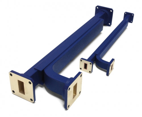
Download the Couplers (Broadwall, Sidewall, Crossguide & Loop) specifications.

02_waveguide_directional_couplers_1.0b_new.pdf

Reviews

No product reviews yet.

Enquire

Add your details below to find out more about this product. We'll aim to get back to within 48 working hours.